MIM Product Design Guidelines: Optimizing Geometry for Best Performance
Metal Injection Molding (MIM) gives designers significant freedom, but to fully realize its advantages, it is essential to understand the physical characteristics of powder flow and sintering shrinkage. Following the five design principles below helps ensure optimal mass production stability and mechanical strength.
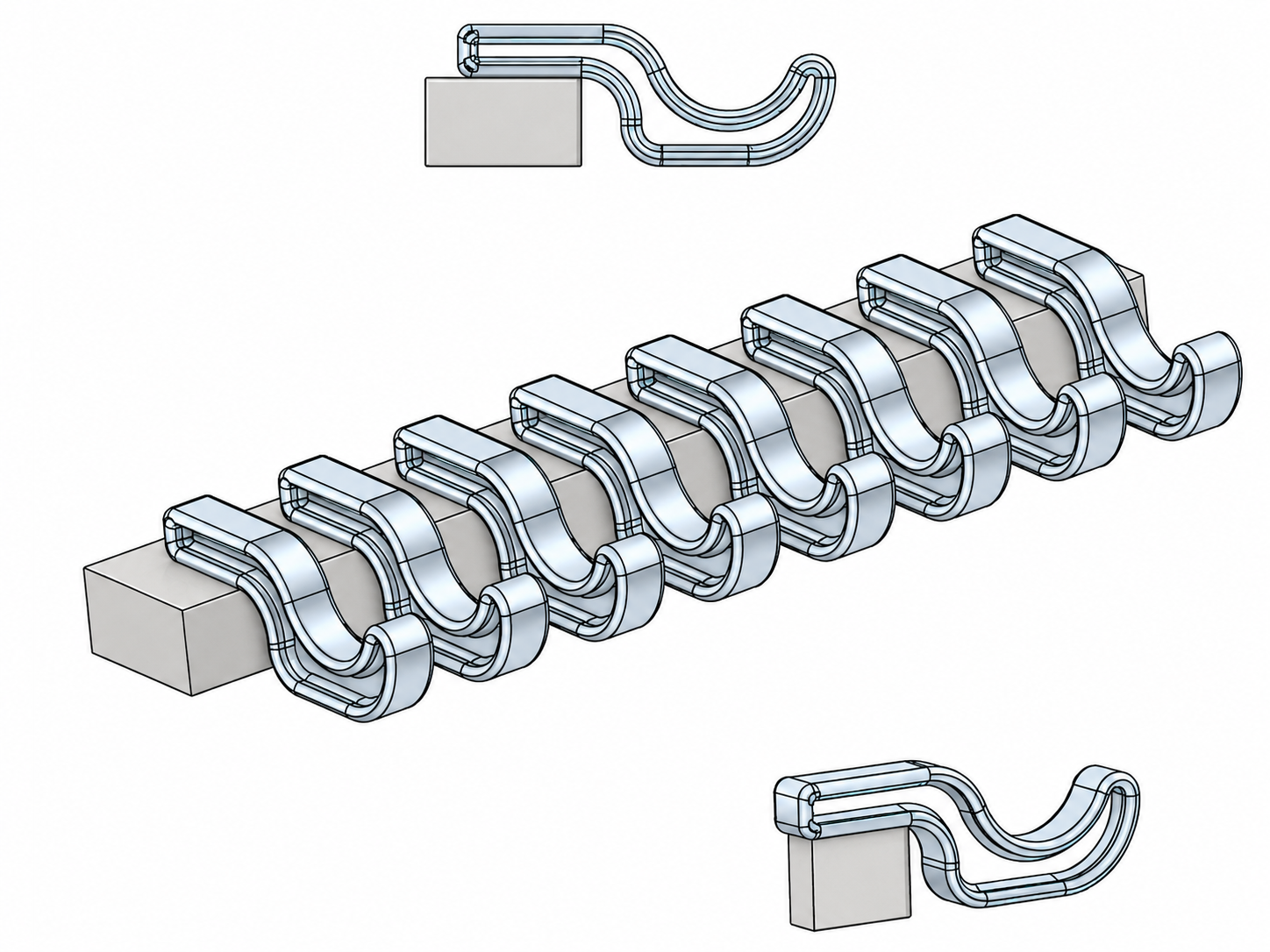
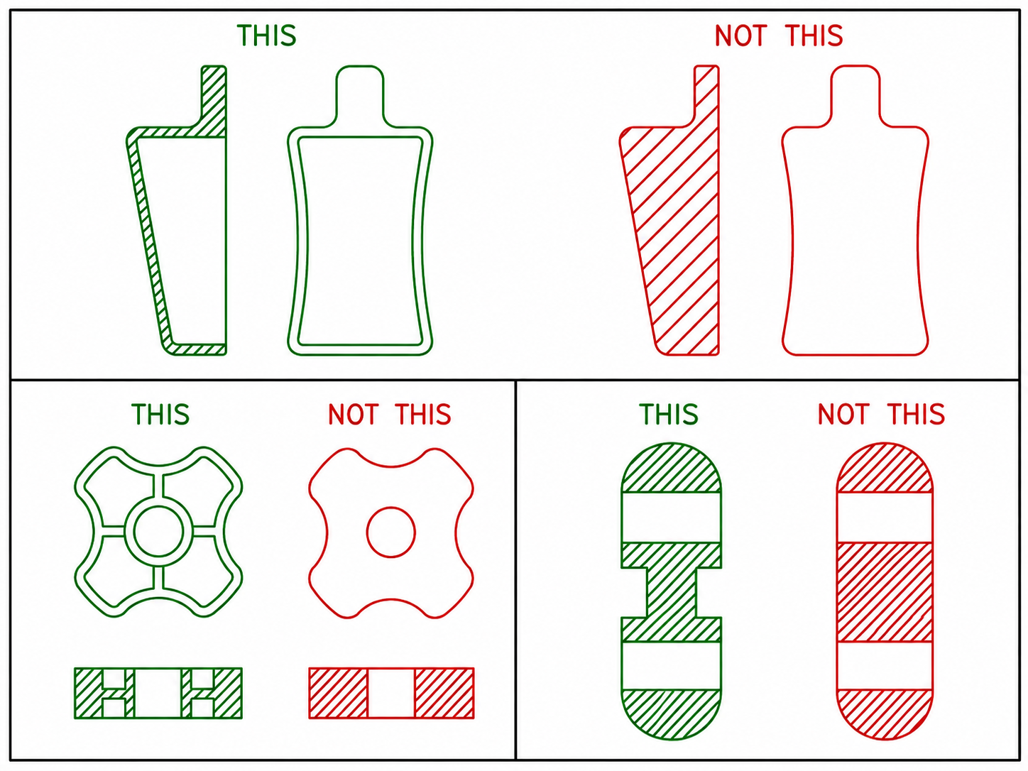
1. Wall Thickness Uniformity
This is the first golden rule of MIM design. During debinding and sintering, uneven wall thickness causes differences in heating and cooling rates, which can lead to internal stress, warpage, or surface sink marks.
Recommended Range
The ideal wall thickness should generally be controlled between 0.5 mm and 5.0 mm.Design Approach
If a thick structure is required, use coring and reinforcing ribs instead of simply increasing solid wall thickness. This helps maintain uniform wall thickness, saves costly material, and shortens debinding time.
2. Draft Angles
To ensure that the green part can be smoothly released from the mold, all feature surfaces perpendicular to the parting line should include draft angles.
Recommended Value
A draft angle of 0.5° to 1° is generally recommended. Areas with surface texture or complex cores may require larger draft angles. Ignoring this requirement may cause drag marks or microcracks during ejection.
3. Avoid Sharp Corners and Stress Concentration
MIM feedstock flows like a liquid inside the mold. Sharp internal corners can restrict flow, cause incomplete filling, or become stress concentration points after sintering, leading to part failure.
Design Approach
Add radii to all corners. A minimum radius of 0.1 mm is recommended. Rounded corners not only improve mold filling, but also significantly enhance the structural strength of the finished part.
4. Sintering Support Considerations
When the green part softens at high temperature in the sintering furnace, it can deform under gravity like soft clay.
Design Approach
The design should preserve a large flat surface wherever possible as the sintering datum, allowing the part to sit stably on the sintering setter plate. If the geometry is special, such as a curved bottom, a dedicated ceramic setter may be required, which will increase production cost.
5. Gate Location
The gate is the entry point where material flows into the mold and it leaves a small mark. During design, the impact of gate location on appearance and dimensional accuracy must be considered. Gates are typically placed on non-functional surfaces or in locations that can be removed through secondary processing. Please mark any “no-gate areas” on the drawing so that mold engineers can design the runner system accordingly.
Following these principles not only improves the dimensional accuracy of MIM parts, which can typically reach ±0.3%, but also ensures quality consistency during high-volume production.